
Battery firmware deserves a colder read than most hobby projects.
If a dashboard crashes, you refresh. If a battery-management system fails in the wrong direction, you can damage cells, start a fire, or create a legal problem.
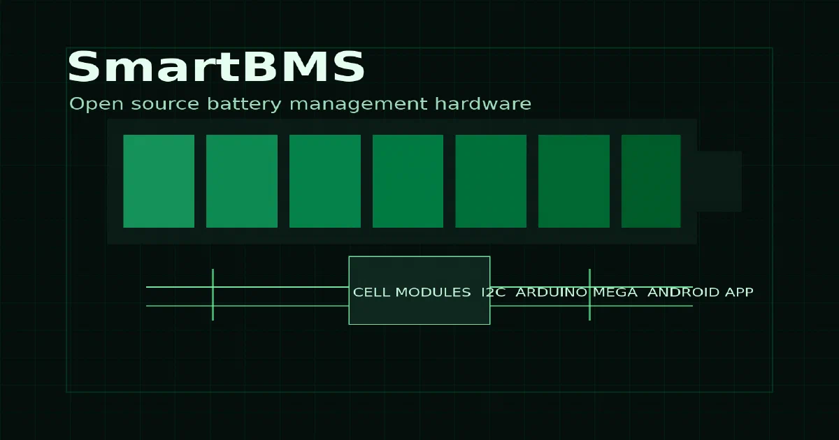
SmartBMS , also published as Green BMS, is an open source smart battery management system for lithium battery packs. It is not just an Arduino sketch. The repo includes hardware designs, firmware, fabrication outputs, electrical drawings, a case drawing, and the Android app source.
That makes it a good Foss Engineer candidate, but with a big caveat: a successful compile is not an electrical safety review.
What is SmartBMS?
SmartBMS is an open source battery management system for lithium cells such as LiFePO4, Li-ion, and NCM packs.
The project is built from four main pieces:
- Cell Module
- Control Unit
- Limiter
- Android App
Each cell module is based on an ATtiny microcontroller. It measures the cell voltage, reads temperature values, performs local balancing through a MOSFET/resistor path, and communicates with the control unit over I2C.
The control unit is based on an Arduino Mega. It polls the cell modules, tracks cell state, calculates pack values, handles charge/discharge/balance/alarm relay outputs, estimates state of charge from current, stores parameters in EEPROM, and talks to a smartphone over Bluetooth.
The limiter is the charge-current limiting part of the design. The Android app is the human-machine interface for status and settings.
Repository Tour
The repository layout is organized by physical subsystem:
01_Documentation/
02_Cell Module/
03_Control Unit/
04_Interface board/
05_Control Unit case/
06_Android app/
07_Limiter/
02_Cell Module/ contains both the KiCad project and the ATtiny cell-module firmware.
03_Control Unit/ contains the Arduino Mega control-unit firmware.
04_Interface board/ contains the KiCad interface board for the Arduino Mega-based control unit.
05_Control Unit case/ contains the LibreCAD DXF for the enclosure.
06_Android app/ contains the MIT App Inventor .aia project.
07_Limiter/ contains the QElectroTech limiter drawing and PDF export.
The repo also includes Gerber and drill files, PDF drawings, KiCad libraries, board archives, and documentation drawings. This is a buildable hardware package, not only a source-code archive.
Hardware Notes
The cell-module KiCad board file reports:
date: 2021-08-24
revision: 0.02
modules: 35
approximate board labels: 62 mm x 42 mm
The interface-board KiCad file reports:
date: 2021-03-29
revision: 4.h.0.01
modules: 63
approximate board labels: 107 mm x 54 mm
The hardware files include typical BMS building blocks: connectors, LEDs, relays, Arduino Mega socket footprints, ATtiny circuitry, balancing resistors, fusing, MOSFET-related circuitry, and supporting passives.
The repository also includes an example wiring PDF, cell-module drawing, interface-board drawing, limiter drawing, and a programming-cable drawing.
Firmware Architecture
There are two Arduino sketches:
02_Cell Module/Software/Attiny_Cell_mod_1_6/Cell_mod_1_6.ino
03_Control Unit/Software/Mega_Control_Unit_2_1/Control_Unit_2_1.ino
The cell-module sketch uses:
#include <TinyWireS.h>
#include <EEPROM.h>
#include "functions_4.h"
#include <avr/wdt.h>
It sends five bytes to the control unit:
cell voltage high byte
cell voltage low byte
temperature 1
temperature 2
life byte
It receives three bytes:
balance command
control-unit life byte
command flags
The cell module also supports address programming with two buttons and LED feedback. The selected address is stored in EEPROM.
The control-unit sketch uses:
#include <Wire.h>
#include <EEPROM.h>
#include <SoftwareSerial.h>
#include <avr/wdt.h>
It keeps an array of 41 cell structures, with the default EEPROM initialization setting the number of cells to 16.
The main loop polls cells sequentially, calculates millivolts, checks high/low/balance/error states, tracks highest and lowest cells, computes pack voltage, reads current from A0, estimates state of charge, drives relays, and sends compact text packets to the Bluetooth HMI.
Default Parameters
The control-unit firmware initializes EEPROM defaults when the first-use marker is missing:
password: 1234
battery capacity: 60 Ah
cells: 16
very high: 3600 mV
very high hysteresis: 3550 mV
high: 3450 mV
high hysteresis: 3420 mV
balance: 3400 mV
balance hysteresis: 3350 mV
low: 2900 mV
low hysteresis: 3100 mV
status delay: 3000 ms
cell timeout: 6000 ms
high cell pole temperature: 45 C
high balance resistor temperature: 80 C
balance delta on: 40 mV
balance delta off: 20 mV
current range: -200 A to 200 A
Do not treat those as universal lithium defaults. They must be checked against the exact cell chemistry, charger, load, wiring, fusing, contactors, and regulations for the pack.
Android App
The Android app source is:
06_Android app/App_inventor_Green_bms_0_0/Green_bms_0_0.aia
The .aia archive identifies itself as built with MIT App Inventor. It contains 31 files, including battery icons from bat0.png through bat100.png, alarm and connection icons, overview/cells/settings graphics, block files, screen files, and project metadata.
The firmware communicates with the app over a Bluetooth serial module at 9600 baud:
SoftwareSerial SSerial(10, 11);
The packets are compact text messages for pages, parameters, graph/status values, and control signals.
Local Field Test
There is no Docker path here, so I compiled the two Arduino sketches with temporary PlatformIO projects.
The Arduino Mega control unit was compiled with:
/tmp/foss-post-speeduino/pio-venv/bin/platformio run \
  -d /tmp/foss-post-smartbms/control-pio \
  -e megaatmega2560
Result:
megaatmega2560 SUCCESS
RAM:   72.2% (used 5912 bytes from 8192 bytes)
Flash: 12.2% (used 31046 bytes from 253952 bytes)
firmware.hex: 87351 bytes
The ATtiny84 cell module was compiled with:
/tmp/foss-post-speeduino/pio-venv/bin/platformio run \
  -d /tmp/foss-post-smartbms/cell-pio \
  -e attiny84
Result:
attiny84 SUCCESS
RAM:   55.7% (used 285 bytes from 512 bytes)
Flash: 70.0% (used 5738 bytes from 8192 bytes)
firmware.hex: 16156 bytes
The ATtiny build produced warnings about TinyWireS callback signatures and the selected tinyX4 pin mapping. Those warnings did not stop the build, but the pin-mapping warning is worth noticing before flashing real hardware.
Battery Safety
The upstream README includes a clear warning: lithium and other batteries are dangerous, the project has no warranties, use is entirely at your own risk, and local laws or regulations may apply.
That is the right framing.
Before building or using a BMS like this:
- Validate the schematic and PCB design.
- Confirm your lithium chemistry and voltage thresholds.
- Use proper fuses, wiring, isolation, and contactors.
- Test with current-limited supplies before using real packs.
- Confirm relay fail states.
- Validate charger behavior with the limiter.
- Check temperature sensing and sensor placement.
- Do not rely on a compile check as proof of safety.
Project Links
Conclusion
SmartBMS is a small repo, but it covers a lot: KiCad boards, Gerbers, electrical drawings, Arduino firmware, Android App Inventor source, and enclosure CAD.
The local software result was good. Both sketches compiled in isolated PlatformIO projects. The bigger question is not whether the code builds; it is whether a builder can safely fabricate, inspect, test, configure, and operate the system for a real battery pack.
FAQ
Is SmartBMS a self-hosted app?
Can I run it with Docker?
What boards does it use?
Did the firmware compile locally?
Is a successful compile enough to use it on a battery pack?
What is the default Bluetooth password?
1234 when EEPROM is reset or first initialized.
Comments