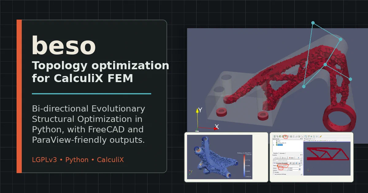

Topology optimization is one of those engineering workflows that sounds expensive by default. You expect a commercial CAD suite, a solver license, and a button hidden behind a simulation workbench.
beso is the opposite shape: a small LGPLv3 Python project that wraps the open-source CalculiX finite element solver and implements BESO, the Bi-directional Evolutionary Structural Optimization method. It is not a polished consumer app. It is a direct, readable, engineering-oriented script kit for exploring where material is actually useful in a loaded part.
What is beso?
beso is Python code for topology optimization using the CalculiX FEM solver.
BESO stands for Bi-directional Evolutionary Structural Optimization: in plain terms, the code repeatedly removes low-value material and can add back material where the current design is overstressed or structurally important.
beso Source Code on GitHub beso Wiki and Examples License: LGPL-3.0 ✅
The normal workflow starts with a CalculiX .inp file. You prepare that model in FreeCAD, Salome, Gmsh, PrePoMax, CalculiX GraphiX, or any other tool that can produce suitable CalculiX input. Then beso runs an iterative loop:
- Generate a modified CalculiX input file for the current element states.
- Run the external
ccxsolver. - Parse stresses, energy density, heat flux, displacements, or buckling results.
- Compute sensitivity values for each design element.
- Apply filters to reduce checkerboard artifacts or enforce simple constraints.
- Switch elements down to softer/lighter states or up to stronger states.
- Export meshes, logs, plots, and VTK files for inspection.
The output is not a finished manufacturable CAD model.
It is an informed material layout: the kind of result you use to remodel a bracket, rib, beam, or support with better intuition.
Why it is interesting
Most open CAD discussions focus on modeling: FreeCAD, OpenSCAD, CadQuery, SolveSpace. beso sits one layer deeper in the engineering workflow.
It asks: given a mesh, loads, constraints, materials, and a target mass, where should material remain?
That makes it useful for:
- Early structural design: Explore load paths before committing to a final CAD model.
- Open FEM workflows: Keep the solver side in CalculiX instead of a proprietary package.
- Hackable optimization: Read and modify the Python implementation rather than treating it as a black box.
- FreeCAD users: Use the included FreeCAD macro to generate configuration from a FEM analysis.
- ParaView users: Inspect
.vtkoutputs and threshold element states visually.
The project is small enough to understand.
The tradeoff is that you need to bring engineering discipline: validated load cases, mesh quality, solver sanity checks, and post-optimization verification.
How beso Works
The source tree is intentionally flat:
beso_main.py       # Optimization driver
beso_conf.py       # User-editable Python config
beso_lib.py        # CalculiX parsing, writing, switching, exporting
beso_filters.py    # Sensitivity/state filters
beso_plots.py      # Matplotlib plots
beso_separate.py   # Node separation helper
beso_fc_gui.py     # Experimental FreeCAD macro
shell.nix          # Python/numpy/matplotlib dev shell
wiki_files/        # Example files and result images
beso_main.py owns the loop. It sets defaults, executes beso_conf.py, imports the .inp mesh, identifies optimized domains, computes initial mass, prepares filters, and then starts writing file000, file001, and following CalculiX jobs.
The objective is controlled by optimization_base:
| Mode | What it uses |
|---|---|
stiffness |
Element energy density, for stiffness/compliance-style optimization |
failure_index |
Failure index divided by effective density |
buckling |
Lowest buckling factor, with nearby modes blended |
heat |
Heat flux through the structure |
The central trick is state switching. Instead of deleting elements and remeshing every iteration, beso assigns each element a state.
A two-state problem often uses a “void-like” material with tiny stiffness/density and a normal solid material.
The mesh stays intact, CalculiX can still solve it, and the optimizer can track element histories.
Configuration Model
The main configuration file is beso_conf.py. It is not YAML or TOML. It is Python code executed by the optimizer, which means it is flexible but should be treated as trusted local input.
A minimal design-domain section looks like this:
path = "."
path_calculix = "/usr/bin/ccx"
file_name = "Plane_Mesh.inp"

elset_name = "design_space"
domain_optimized[elset_name] = True
domain_density[elset_name] = [1e-6, 1]
domain_thickness[elset_name] = [1.0, 1.0]
domain_FI[elset_name] = [
    [("stress_von_Mises", 450.0e6)],
    [("stress_von_Mises", 450.0)]
]
domain_material[elset_name] = [
    "*ELASTIC \n210000e-6, 0.3",
    "*ELASTIC \n210000, 0.3"
]

mass_goal_ratio = 0.4
filter_list = [["simple", "auto"]]
optimization_base = "stiffness"
save_resulting_format = "inp vtk"
The important thing is that elset_name must match an element set in the CalculiX input file. This is how beso knows which elements belong to a design domain and which should remain fixed as non-design geometry.
Running beso Locally
There is no Docker Compose setup for this project, and that is appropriate. beso is not a server.
It is an engineering script that depends on a local solver binary and local analysis files.
Pre-Requisites
Install:
- Python 3
- NumPy
- Matplotlib
- CalculiX
ccx2.17 or newer - FreeCAD 0.18 or newer if you want the macro workflow
- ParaView if you want comfortable
.vtkinspection
The repository also includes shell.nix for a Python environment with NumPy and Matplotlib, but it does not install CalculiX for you.
Clone the project:
git clone https://github.com/calculix/beso
cd beso
Check the Python side:
python3 -m py_compile beso_main.py beso_lib.py beso_filters.py beso_plots.py beso_separate.py
Prepare a working directory containing your CalculiX .inp file, configure beso_conf.py, and run:
python3 beso_main.py
You can also override the configured input filename:
python3 beso_main.py Analysis-1.inp
For FreeCAD users, the wiki recommends starting with the GUI macro example.
Copy the Python files into the FreeCAD macro directory, open a FEM analysis, run beso_fc_gui.py, select the analysis file, choose material/thickness domains, set the filter range and mass goal, then generate the configuration and run the optimization.
Outputs You Actually Inspect
The useful artifacts are practical engineering files:
analysis_name.logfor settings, progress, warnings, and errors.fileNNN.inpfor generated CalculiX inputs.fileNNN.vtkfor iteration-level inspection in ParaView.fileNNN_res_mesh*.inpfor resulting meshes by element state.resulting_states.vtkfor the element-state evolution across iterations.Mass.png,FI_mean.png,FI_max.png, andFI_violated.pngfor convergence and stress tracking.- Optional
.csvexports with element centers, states, sensitivity values, and failure-index data.
The bundled wiki examples are worth reading before running your own part.
They cover a simply supported 2D beam, an engine bracket, an airplane bearing bracket, and the FreeCAD GUI workflow.
Field Note From Local Trial
I tested the repository in a local Linux workspace on 2026-09-04 with Python 3.12.3, NumPy 1.26.4, and Matplotlib 3.6.3.
The Python modules compiled successfully:
python3 -m py_compile beso_main.py beso_lib.py beso_filters.py beso_plots.py beso_separate.py
I did not run a full optimization because no ccx, calculix, or ccx_2.17 executable was available in PATH. That means this check validates the Python syntax/import side only, not solver behavior or numerical correctness.
Where beso Fits
Use beso when you are comfortable with FEM and want a transparent topology-optimization loop around open tooling.
Do not use it as a one-click replacement for commercial generative design.
The wiki itself is careful about this: BESO is heuristic, input parameters influence result quality and convergence speed, and the output usually needs smoothing, remodeling, and verification.
That is still valuable. For early design, a rough optimized mesh can tell you where the load paths want to be.
From there, you can redraw the part in FreeCAD, validate it with a cleaner analysis, and make actual manufacturing decisions.
Good Alternatives And Neighbors
- FreeCAD - open-source parametric CAD with FEM workbench and CalculiX integration.
- CalculiX
- the FEM solver used by
beso. - ParaView - practical viewer for VTK outputs and threshold filtering.
- PrePoMax - CalculiX-focused pre/postprocessor for Windows.
- Salome - open platform for geometry and meshing workflows.
Conclusion
beso is a compact open-source topology-optimization tool for people who are willing to work close to the FEM files.
It is not trying to hide CalculiX, FreeCAD, ParaView, or the configuration details. It exposes them.
That makes it a useful project to study even if you never run it in production.
The code shows how a solver-backed optimization loop can be built with plain Python, file-based interfaces, and enough engineering glue to turn repeated FEM solves into a material-layout workflow.
FAQ
Is beso self-hosted software?
How does beso relate to FreeCAD?
Think of FreeCAD
as the CAD/FEM workbench and beso as an optimization loop that can sit beside it.
FreeCAD can create the geometry, define materials, mesh the part, set loads and constraints, and export the CalculiX .inp analysis file. beso then reads that .inp, rewrites element states across iterations, runs CalculiX, and produces optimized mesh/result files that you can bring back into FreeCAD or inspect in ParaView.
That means the FreeCAD post is the better starting point if you are still setting up open-source CAD, FEM, or headless design automation.
This beso guide picks up once you already have a valid CalculiX analysis and want to explore topology optimization around it.
Can I use beso without FreeCAD?
.inp files. You can prepare those files with other tools as long as the element sets and solver output match what beso expects.
Does the result become a finished CAD model?
Why no Docker Compose snippet?
beso is not a deployable service. Its real dependencies are a local CalculiX solver, Python numerical libraries, and engineering input/output files. A generic container would hide the important part: validating the solver path, model files, and local preprocessing/postprocessing workflow.
Comments